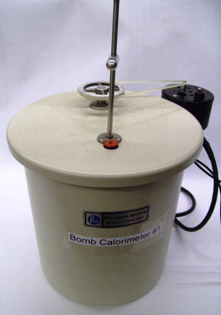
Adiabatic constant volume ‘Bomb’ calorimetry is a common experimental system for experimental measurement of combustion reactions. The Parr 1341 plain jacket calorimeter is shown in Fig. 1. It consists of an insulated jacket through which the leads for the ignition system run, a metal bucket which will hold the water that serves as the medium through which we will monitor the heat released by the reaction in the bomb and a cover through which the temperature probe and the stirring shaft run. The stirring shaft has a propeller at the bottom and a wheel at the top, which is attached to the stirring motor mounted on the side of the calorimeter with a rubber belt. Also on the calorimeter’s cover is a metal rod which can be used to keep the temperature probe (not shown in this view) in a vertical position not touching the metal bucket.
The Parr model 1108 oxygen combustion bomb, shown in Fig. 2, is used in conjunction with the 1341 calorimeter. It is constructed of stainless steel and can withstand pressures in excess of 30 atm, but it can fail unexpectedly (there is a reason why it is called a bomb, and should therefore be treated with the utmost care and respect at all times). The top of the bomb is held in place by a collar that screws down on to the main body of the bomb. There is a rubber gasket between the main body and the top assembly that helps to seal the bomb against loss of pressure (see Fig. 3). The exact arrangement of this seal is different for the two bombs in the laboratory, but its function is the same for both. Protruding from the top assembly is the filling port, the pressure release valve and the two electrode posts to make the electrical connections for starting the combustion reaction. The filling port is simply a metal rod with an o-ring attached that will admit gas to the bomb when the outside pressure is greater than the internal pressure, but which will not allow gas to escape when the internal pressure is greater than the outside pressure.
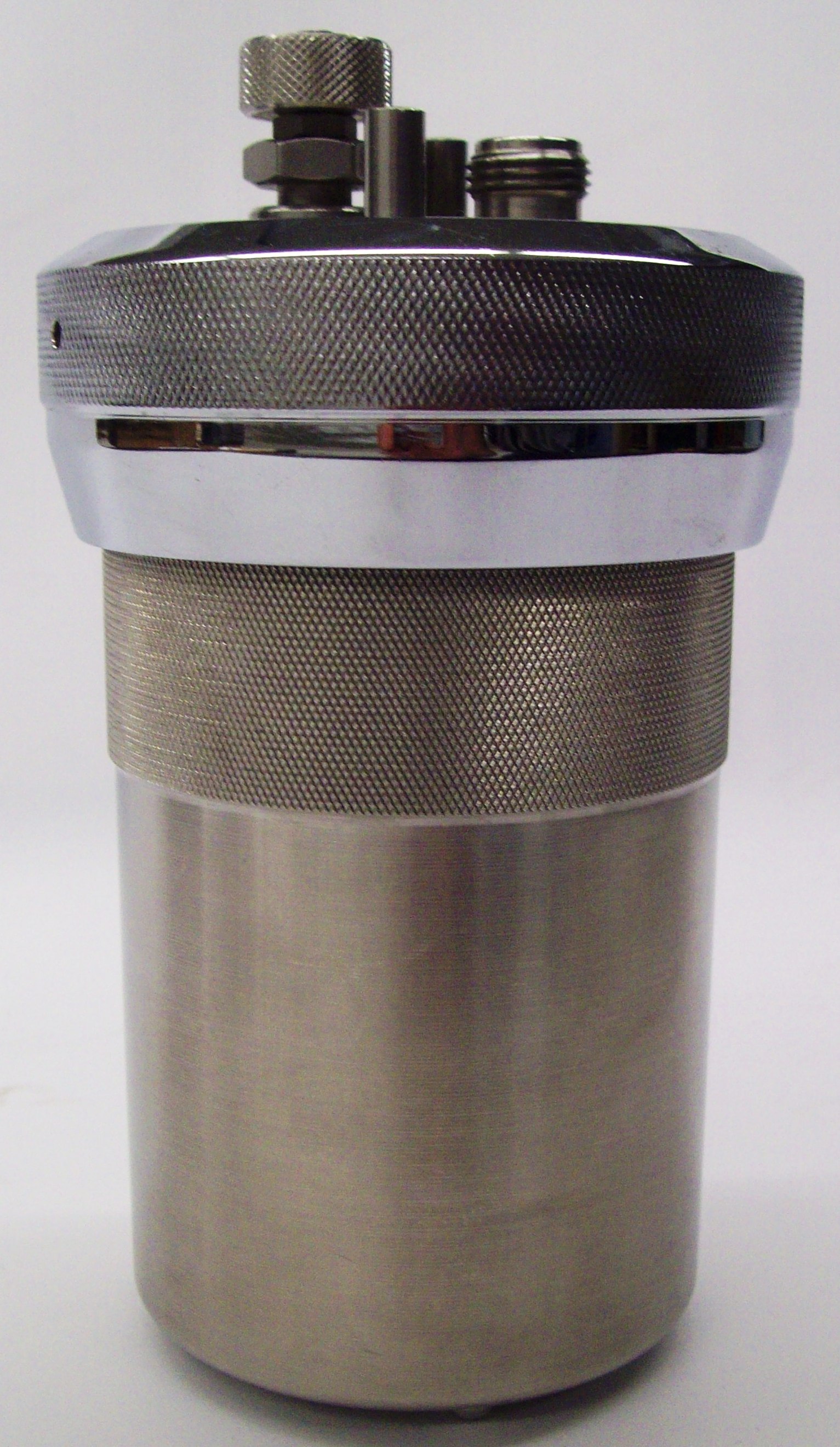
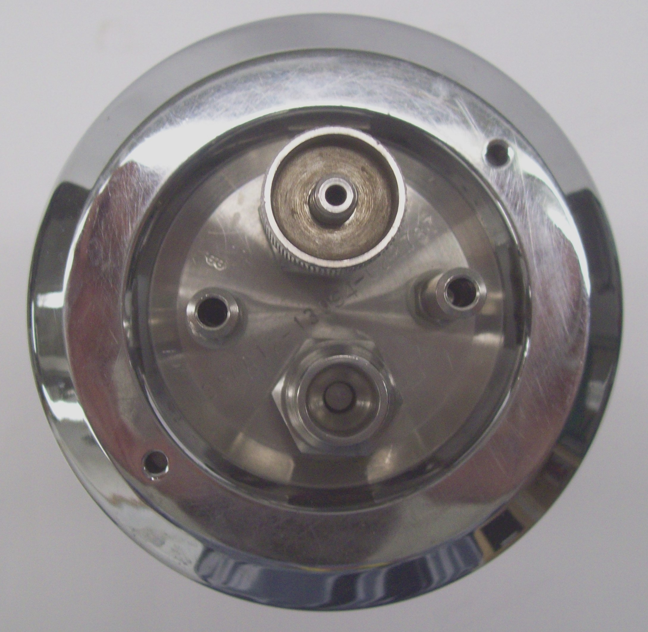
Figure 2. Side view (left) and top view (right) of the Parr model 1108 oxygen combustion bomb. In the top view the filling port is on the bottom, the pressure release valve is on the top and the electrode posts are on either side.
The top assembly slides out of the bomb to reveal the rest of the bomb’s components, as shown in Fig. 3. The two electrode leads extend downward; one is longer and is bent into a circle to accommodate the combustion cup, while the other simply ends about 1 cm above the combustion cup. On each lead there is a metal sleeve that slides up to reveal a hole through which the fuse wire will be run. Once the wire is in place, these sleeves slide down to hold the wire firmly in place until ignition. The combustion cup rests snuggly on top of the loop formed by the electrode lead. When a sample is present in the cup, one must check that the cup is securely in place to prevent sample loss resulting in poor results and a contaminated bomb.
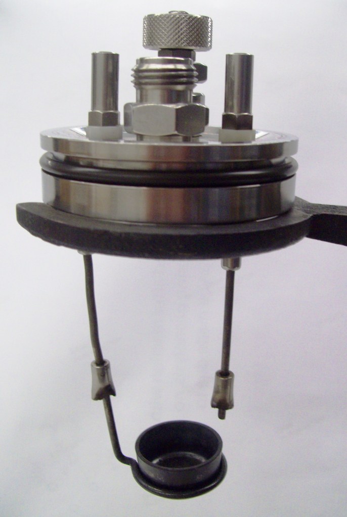
Before beginning any experiments, be sure that the bomb is in good condition (no obvious damage to the main seal or the bomb body) and is clean and dry. Report any damage to your instructor immediately. CAUTION! A damaged bomb or main seal can lead to the bomb’s catastrophic failure and result in severe injury or death. Helpful hint: when you assemble the calorimeter on your bench, position the calorimetry thermometer and the computer as far from the calorimeter as possible. This will prevent damage to these expensive items in the unlikely event of a bomb failure. The Parr ‘filling station’ consists of a clamp where the bomb can be held in place during filling and a flat metal support on which the bomb head may be placed to position the sample and wire (see Fig. 3). The sample is placed in the combustion cup either as a pellet (for a solid sample, see below for the procedure to make a pellet) or as a neat liquid, if the liquid is sufficiently non-volatile. Volatile liquid samples may also be placed in the cup, but the cup must then be covered with a special tape (available from Parr) to minimize evaporation during the filling process. Volatile liquids may also be placed in a capsule designed for calorimetry (also available from Parr). The sample’s mass must be precisely known (to the nearest 0.1 mg) and must not exceed the amount given in your procedure. CAUTION! Exceeding the recommended mass will mean that more heat will be evolved than expected and may lead to violent, catastrophic failure of the bomb resulting in serious injury or death
The Parr pellet press (Fig. 5) form a pellet of a solid sample. To prepare the press, be sure that the die press assembly (Fig. 5, middle) is clean and dry. Assemble the die press assembly (Fig. 5) and weigh out approximately the amount of solid that you will need (a top-loading balance may be used). Place it in the opening in the die press assembly. If the solid is not granular, you may have to pack it down with a spatula so that all of the sample will fit in the die. Place the loaded die assembly into the pellet press (Fig. 5, right). IMPORTANT! There is only one correct way to do this. Check that the press’s hammer slides easily into the die assembly as the press’s lever is moved down; reposition the die and/or the hammer, as needed. Carefully pull the pellet press lever down so that the hammer compresses the sample. Pull the lever all the way down to complete forming the pellet (you will feel a definite stop when the pellet has been formed, do not apply any force to the lever after this point is reached). It is important that you do not over-compress the sample (pellets that are too solid will not burn completely). You only need to apply enough pressure to give a pellet that will hold together during handling.
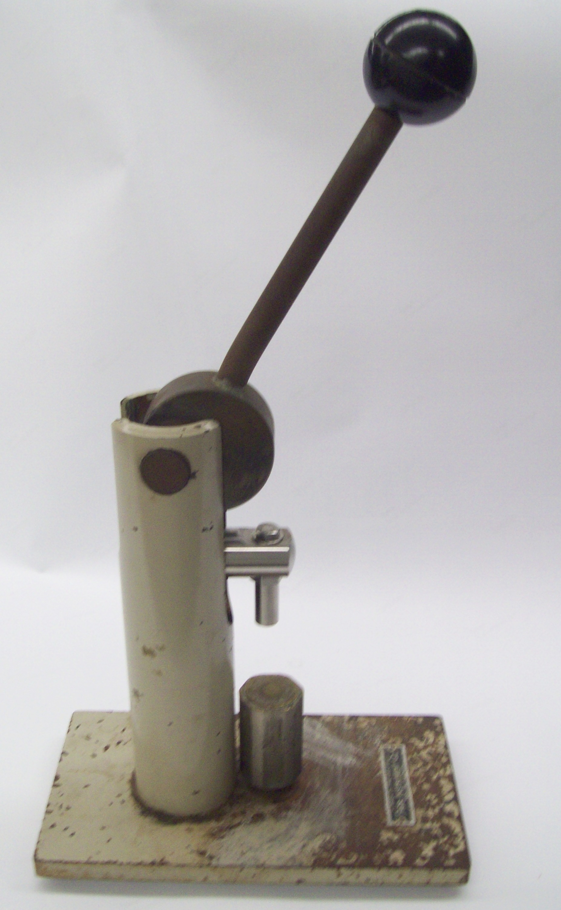
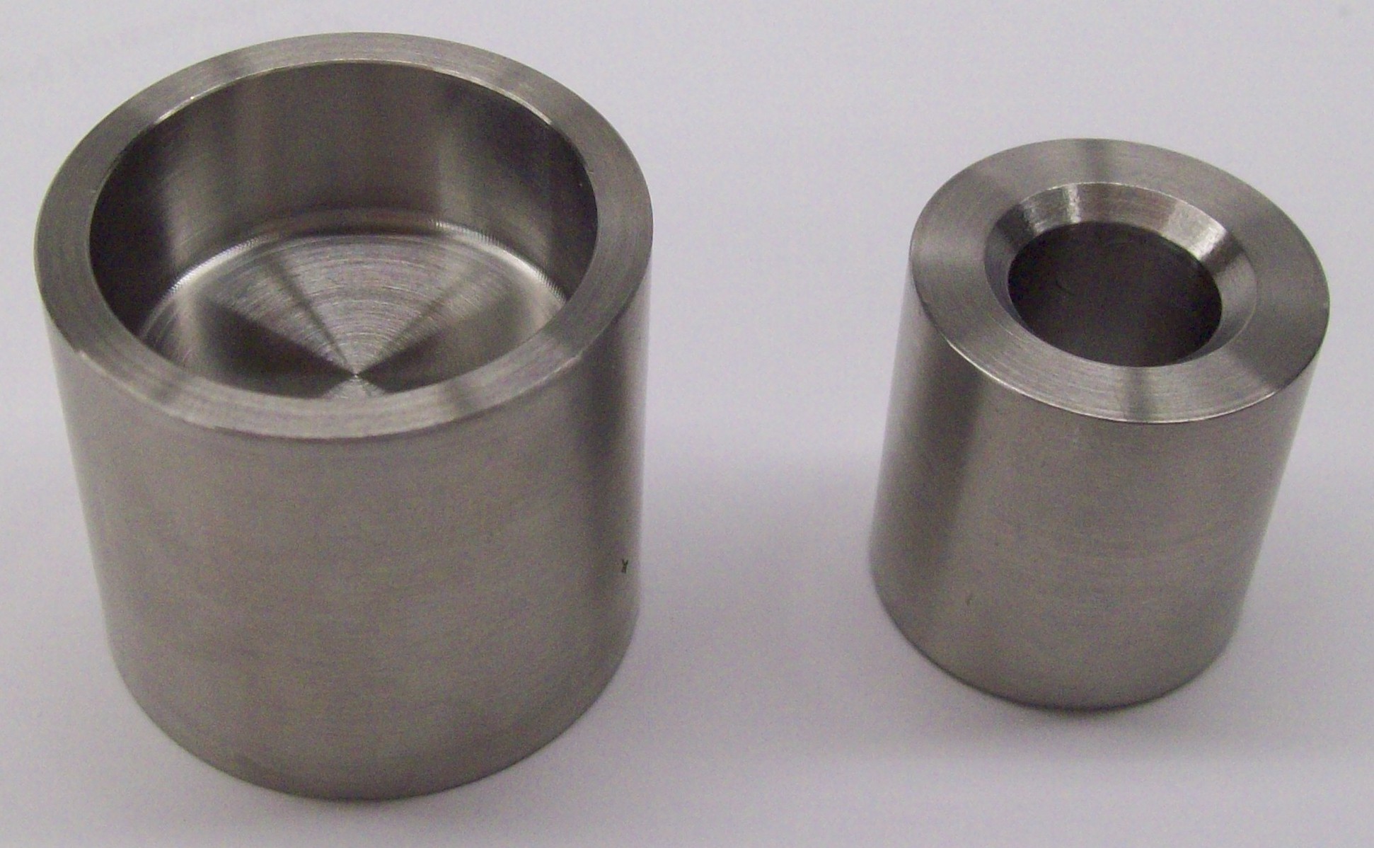
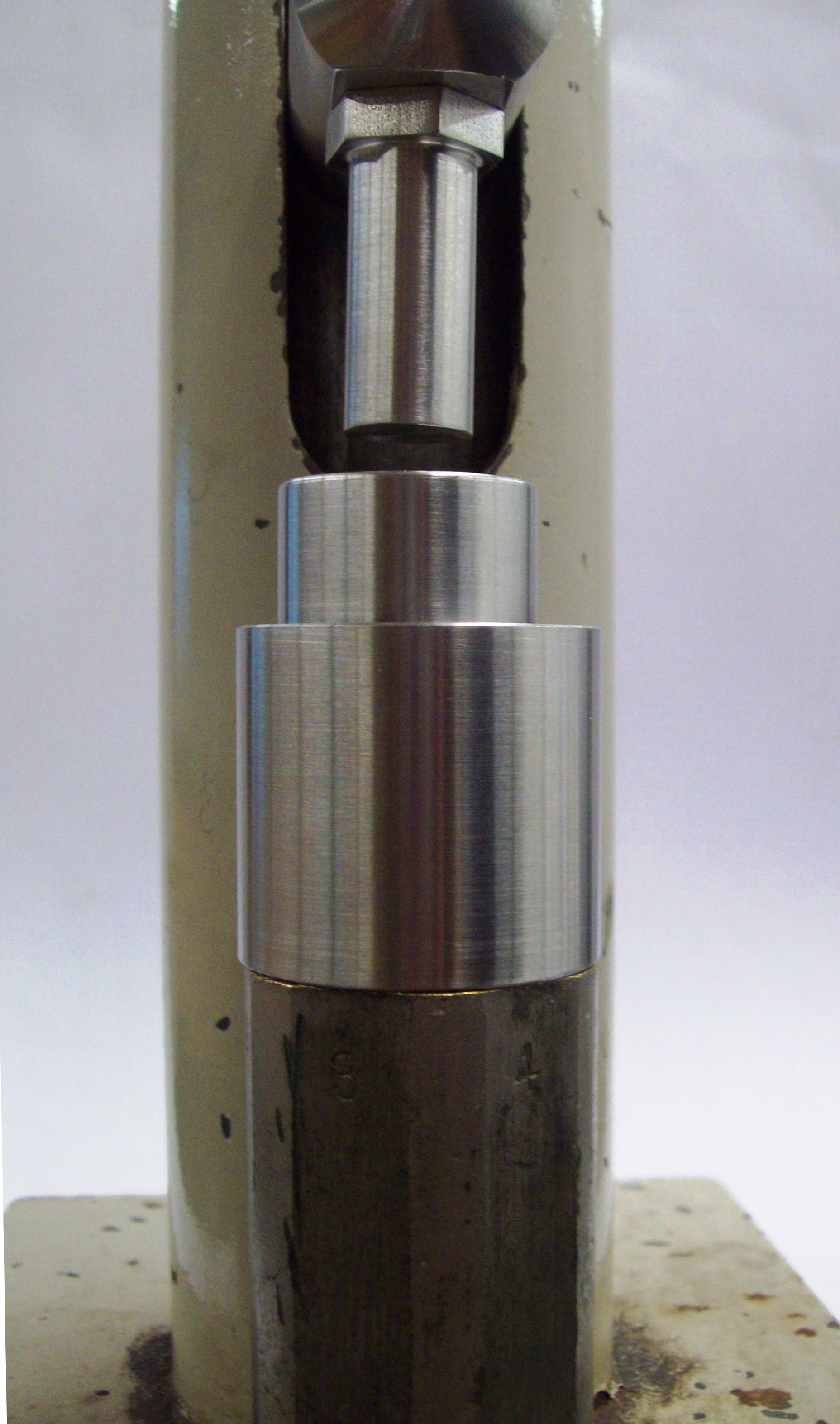
Figure 5. Picture of a Parr pellet press, die press assembly and die press assembly in its proper location in the pellet press.
To remove the pellet, lift the arm and remove the die assembly from the press. Flip the bottom piece of the die assembly over and place the part containing the sample pellet on top, as shown in Fig. 8. Note that there is now space below the top part of the die assembly. Return the die assembly to the press and lower the arm to force the pellet from the die. From this point forward, handle the pellet using only forceps. Weigh the pellet to the nearest 0.1 mg using an analytical balance and transfer it to the bomb’s combustion cup, which has already been positioned as shown in Fig. 3. Be careful not to lose any of the sample during this process. Once the sample is in place, cut a 7-cm length of nichrome ignition wire and either measure its length to the nearest 0.01 cm or obtain its mass to the nearest 0.1 mg (note that obtaining the mass is often easier and gives more precise results). A 7-cm wire should be sufficiently long for our bombs, but if it is not you may use a 10-cm piece of ignition wire. Slide up the sleeve on one of the leads, and place one end in the ignition wire through the hole with about 1 mm of wire extending through the hole. Slide the sleeve down to secure the wire in place. Repeat with the other lead. Using forceps, position the wire so that it presses down on the pellet. This does not need to be a particularly tight connection; it only needs to be sufficient to keep the pellet from moving. For a liquid the ignition wire should be positioned just above the sample. It is critical that the wire does not touch the combustion cup. Once the wire is in place, test the resistance between the electrodes. There should be some non-infinite resistance if everything has been assembled correctly. If the resistance is infinite, check that the sleeves are firmly holding the wire in place and that there are no breaks in the wire.
Place the bomb head into the bomb. Be sure that the pressure release valve is open before you attempt to put the bomb head into the main body of the bomb. On the first run of the day, you might consider running a thin film of water (a wet finger works well for this) around the seal to give a better seal. Some authors suggest that 1.00 ml of distilled water be pipetted into the bomb to aid in condensing the water formed by the combustion reaction.3 It is left up to you whether you wish to follow this procedure, or not. You will be able to feel when the bomb head has been fully inserted and if it is seated properly the top of the bomb head should be level with the top of the main body of the bomb. Once the bomb head is seated properly, place the collar on the bomb and tighten until it is hand-tight (you will feel a definite stop when it is tightened properly). Check the resistance between the leads again. If there is an infinite resistance, disassemble the bomb and find the cause.
The bomb is filled with high-quality oxygen from a standard cylinder using the regulator shown in Fig. 9. The regulator should be already on the oxygen cylinder when you arrive with the main cylinder valve (located on the top of the cylinder) closed. If the regulator is not in place, remove the protective cylinder cap and connect the regulator to the cylinder (note that gas cylinders have different connections depending on what gas is in the cylinder so that a regulator for one gas cannot be placed on the cylinder of an incompatible gas). Tighten the collet finger-tight at first and then use an adjustable wrench to tighten it the last quarter turn, or so. Do not over-tighten! This does not make the regulator leak less, rather it damages the brass fittings and causes leaks. With the regulator’s control knob closed (turned fully to the right, but not too tight), open the cylinder’s main valve (on the cylinder’s top). The needle on the small pressure gauge, which indicates the pressure in the tank, should come up and no hiss of escaping gas should be heard. If the gauge does not register any oxygen pressure or if it reads less than 30 atm of pressure, you cannot proceed. Bring this to your instructor’s attention immediately. If you hear any hissing, turn off the cylinder’s main valve and open the regulator’s control knob to vent the regulator. Check that the regulator was seated properly on the cylinder (you will probably need to loosen the collet), tighten the collet again, and try the pressurization procedure again. If the regulator is still leaking, consult your instructor. When not in use the cylinder’s main valve should be closed and the regulator vented.
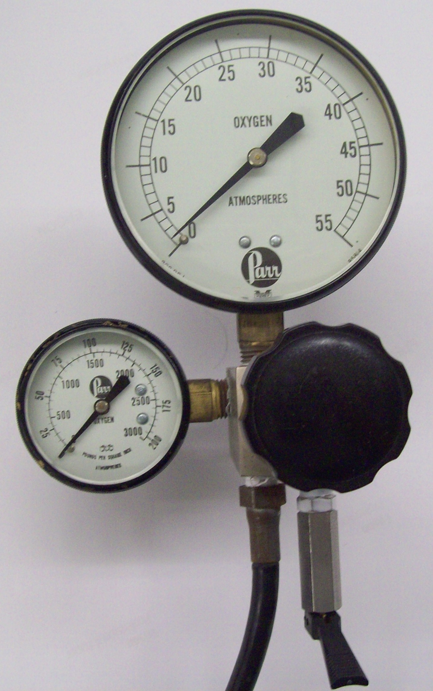
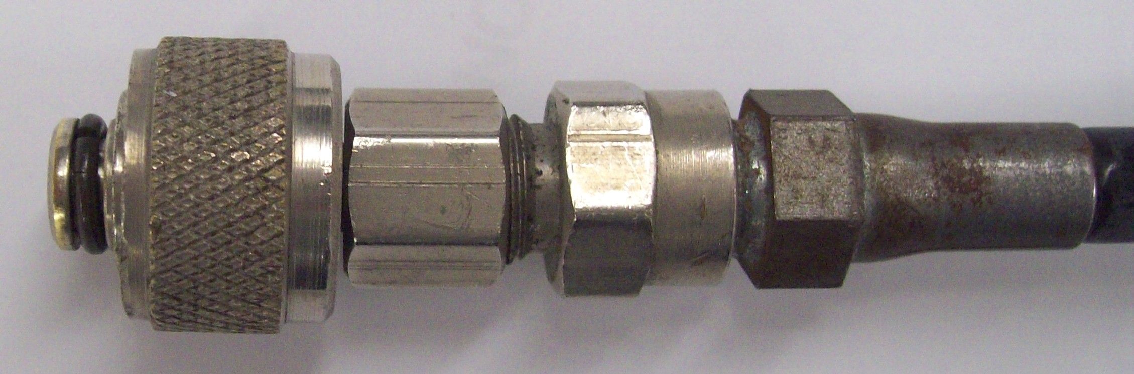
Figure 6. Oxygen regulator used to fill the Parr 1108 combustion bomb (left) and close-up of the connector that links the bomb fill port to the regulator (right). The small gauge in the left-hand picture shows you the oxygen pressure remaining in the tank (i. e., the input pressure) while the large gauge shows the pressure in the bomb when it is attached. The large knob on the front of the regulator controls the gas flow from the oxygen cylinder to the bomb (turning to the right increases the flow, turning to the left decreases the flow). The toggle valve on the regulator’s lower right is the pressure release valve, which should automatically vent the system if the maximum pressure is reached, but can be tripped manually at any time to release the pressure.
Inspect the o-ring on the connector between the bomb and regulator (see Fig. 6). If it has obvious damage, alert your instructor so that the o-ring my be replaced. Connect the oxygen inlet line to the bomb’s fill port (insert the connector until it stops and then tighten the collet finger-tight). With the pressure release valve open, start a gentle flow of oxygen through the bomb by opening the regulator valve slightly. Let the oxygen flow for a few seconds and then close the bomb’s pressure release valve. Slowly fill the bomb to no more than 30 atm of pressure. There should be no leak at the connection between the bomb and the regulator. If there is, shut off the oxygen flow and vent the system, then try loosening and re-tightening the connection. If this does not help, there is probably something wrong with the o-ring or the bomb’s filling port and you should seek your instructor’s assistance. At 30 atm, close the regulator valve and trip the regulator’s pressure release valve to vent oxygen from the line between the regulator and the bomb. If you exceed 30 atm the regulator’s pressure release valve should open to vent oxygen. When this happens, shut off the regulator’s oxygen supply valve, fully open the regulator’s vent valve, then vent the bomb and fill again. Note that if you exceed 30 atm the regulator’s pressure release valve will probably need to be reset which requires disassembly of the regulator and will cost you valuable time. Pressurize the bomb to 30 atm again, but do not vent after the second fill. Disconnect the bomb from the regulator, check the resistance between the leads, and if the resistance is good, you are then ready to proceed to the combustion step.
Check that the calorimeter bucket is clean and dry before you place it into the calorimeter. Lower the bomb into the bucket using the bomb lifter (the bomb should sit on an indentation in the bucket on the side opposite the stirring motor). Check the resistance between the ignition leads one last time. Attach the ignition leads to the bomb, but be sure that the leads are not attached to the ignition unit to prevent any unexpected ignitions. Carefully pour 2 l of deionized water from a volumetric flask into the bucket. It is essential that this volume is as close as possible to 2 l each time . It is helpful, but not essential, that the deionized water be close to room temperature. This may be accomplished by allowing the filled flask to sit on the bench while you make the other necessary preparations. There should be no gas bubbles coming from the bomb at this point. A bubble, or two, should not concern you (this is probably air trapped under screw cap escaping), but a steady stream might indicate a leak. DO NOT CONTINUE if there is a steady stream of bubbles escaping from the bomb and immediately consult your instructor. Place the lid on top of the calorimeter (it only goes on one way) and attach the belt to the stirrer and the motor. Place the temperature probe in position (see the instructions for either the Parr 6772 calorimetry thermometer or the Parr 1661 calorimetry thermometer for information on how to set up the appropriate calorimetry thermometer). The probe fits through the support and should be carefully inserted through the septum. Be sure that the probe is in the water, but not touching the bottom or the sides of the bucket. Start the motor and check that the stirrer and motor are moving freely. Begin acquiring data according to your procedure and the thermometer instructions. A helpful starting point may be to acquire data every 30 sec for about 5 min before the ignition.
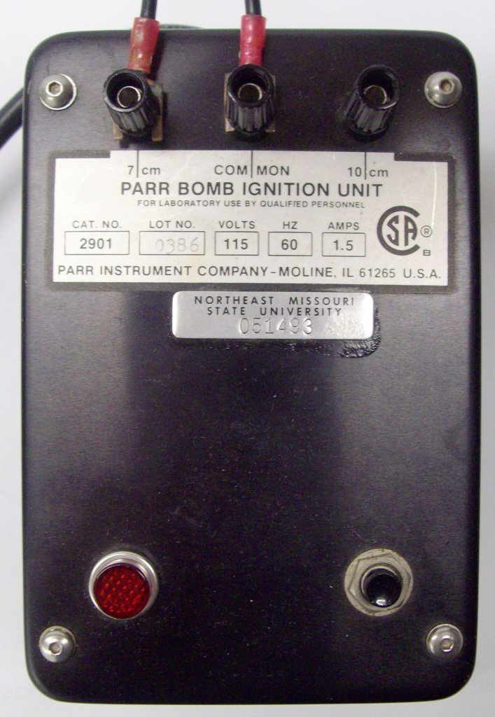
After a sufficient amount of pre-ignition data have been obtained, be sure that the ignition unit is unplugged and then connect the bomb leads to the ignition unit (one of the units is shown in Fig. 7, the other is similar). One lead should be connected to the COMMON terminal and the other to either the 7 cm or the 10 cm terminal, depending on the length of wire you ignition wire that you used (in Fig. 7 the ignition unit is properly configured for a 7-cm ignition wire). Plug in the ignition unit. When you are ready to start the combustion, stand away from the bomb and press the firing button (black button on the lower right side of the unit in Fig. 7). CAUTION! Stay clear of the bomb during firing. You will hear a buzzing noise and the red light will briefly light. If the ignition was successful you should see a temperature rise within about 1 min. If no temperature rise is observed, you can try pushing the ignition button again. However, if no change in temperature is seen after a second ignition attempt, one must assume that the run failed. After a successful ignition continue acquiring data (5 min post-ignition is usually sufficient).
To remove the bomb from the calorimeter, first unplug the ignition unit and disconnect the leads. Shut off the stirring motor and remove the drive belt. Remove the calorimeter’s lid, being careful where you set the lid if the temperature probe is still attached (there is a metal ring that may be attached to a ring stand that can be used to hold the calorimeter’s lid while it is not in use). Disconnect the leads from the top of the bomb and then carefully remove the bomb from the bucket using the bomb lifter. Place the bomb in a convenient place on the lab bench and carefully crack open the vent valve (there should be a loud hiss of escaping gas). The initial venting should be done slowly and carefully, but once most of the gas has been vented the valve should be opened about three-quarters of full. Remove the collar and slide the bomb head assembly out being careful not lose any pieces of the ignition wire that were not consumed. Inspect the bomb for complete combustion. The presence of soot indicates incomplete combustion and a failed run. Collect the remaining ignition wire, and either measure their lengths or find their mass to the nearest 0.1 mg. Clean (rinse with distilled water) and dry the bomb’s interior (with a paper towel). Be sure to dry the under the sleeves on the ignition leads. Water here often leads to a poor connection between the leads and the ignition wire resulting in a failed ignition. Discard the water in the metal bucket and thoroughly dry it.
If more measurements are to be made, repeat the procedure as needed. If you are done for the day, clean and dry all parts of the calorimeter and bomb. Return all instruments and equipment to their designated storage location, or as instructed. Be sure that the oxygen cylinder is closed at the main tank valve.
References
1. Parr Bulletin 1341, Plain Jacket Calorimeter; Parr Instrument Co.: Moline, IL, 1977.
2. Wilson, L. Y. and Tatum, R. J. Chem. Educ.1985, 62, 902. Click here to view as a PDF file (Truman addresses and J. Chem. Educ. subscribers only).
3. Halpern, A. M. and McBane, G. C. Experimental Physical Chemistry, 3rd Ed.; W. H. Freeman: New York, 2006, p. 5.1-5.15.

1 thought on “Parr ‘Bomb’ Calorimeter”